
- Room
- II-355,356
- Staff in charge
- Mr. Manish Kumar
- Faculty in charge
- Subodh Vasant Modak
- Contact
- 6173
- Web page
- profile.iitd.ac.in/~svmodak
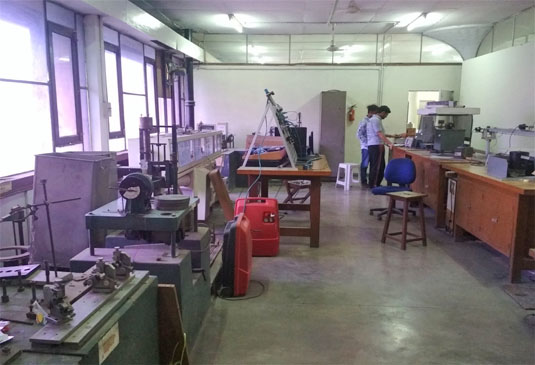
Vibration and Instrumentation Lab offers a wide range of instruments for control labs throughout the academic year, including Couple Drives, Thermocouples, Digital Water Tank, Study of Temperature Transducer, Vertical Take Off and Landing Trainer, DC Motor Study, DC Position Control, Operational Amplifier, RC and RLC Circuit, and Study of Transducer and Instrumentation. Along with the laboratory for controls, practicals for Vibration and Noise Post Graduate studies are also conducted in this lab. Some important instruments are listed below :
Universal Vibration Machine
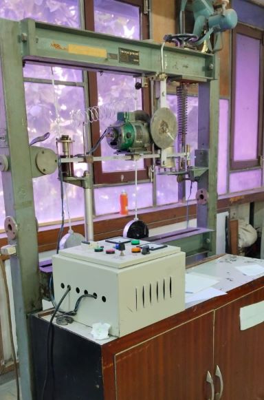
The objective of the above machine is to study free vibration using a universal vibration machine.
Natural frequency and damping factor of a system should be known as their ignorance may lead to serious consequences. A poor vibration-based design can lead to excessive vibration amplitudes, stresses, and untimely failure. At resonance, i.e. when excitation frequency matches with the natural frequency of the system, the amplitude vibration becomes excessive for small damping and decreases with an increase in damping. It is very important that the working excitation frequency should be reasonably away from the natural frequency and if it can’t be ensured, then adequate damping should be provided so that the amplitudes of vibration are within the safe limit. Free vibration response-based logarithmic decrement approach and forced vibration-based half-power method can be used to quantify and assess the level of damping in the system. These methods can also provide information about the natural frequency of the system. If the amplitude resonance peak of the vibration is not perceivable due to higher damping, or even otherwise, the phase plot (phase vs. frequency) can give an indication about the resonance.
Three Rotor System
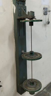
The above instrument is used to Investigate the free vibration characteristic of a degenerate multi-DOF system (3-rotor torsional vibratory system), and also finds the natural frequencies and verifies the corresponding mode shapes.
Pitching and Bouncing
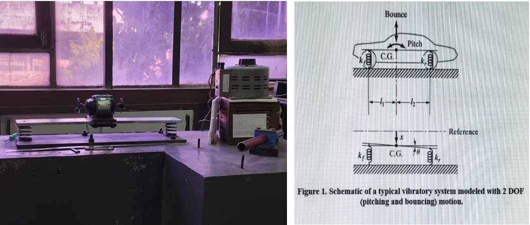
The objective of the above setup is to Study of coupled and uncoupled pitching and bouncing motion of a typical vibratory system. Many mechanical systems like bikes and cars can be modeled as two degrees of freedom systems with both vertical bounce degrees of freedom as well as possible pitching motion (angular motion) (See Figure 1). It is possible to then find if these motions are uncoupled (independent of each other) or coupled (simultaneously occurring). Like you may have experienced a simultaneous pitch and bounce motion when the vehicle brakes suddenly. For such systems, knowledge of the conditions for which the system has coupled or uncoupled sets of natural frequencies helps in better design. It is also important to know these frequencies so that the designer can tune the parameters of the system to ensure that the natural frequencies are well away from the excitation frequencies (engine orders/harmonics in the case of IC engine-based automobiles). In this experiment, we will have a visual feel of the bounce and pitch vibratory motions of a simple representative system in both coupled and uncoupled modes. We would understand the conditions for the uncoupling of the two motions. Which one of the two modes (bounce mode/pitch mode) of vibrations is excited will also be known from the experimental settings. Although the system itself has inherently both modes of vibration possible, however, the excitation conditions dictate which one (or both) will get excited into resonance condition. This aspect will be understood through the experimental observations.
Multi-story building
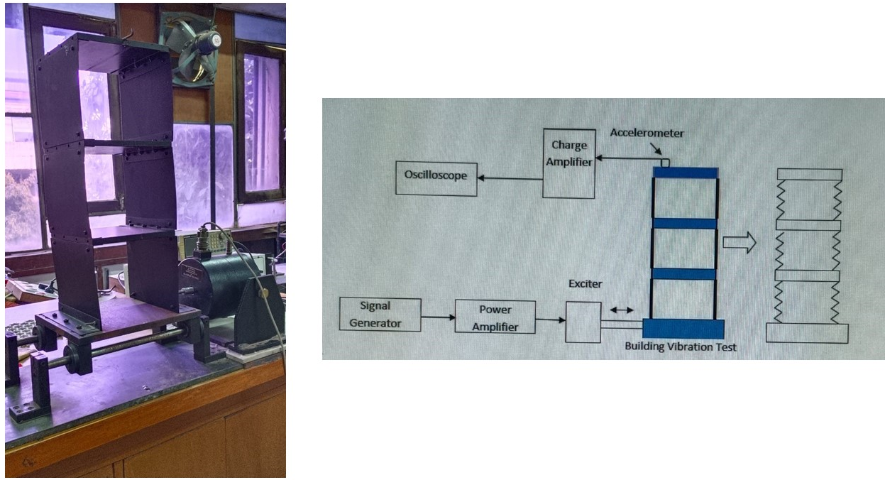
To determine the natural frequencies and corresponding mode shapes of a multi-DOF vibratory system simulating a 3-story building and verification of functioning and design principles of an absorber for controlling vibration. The test setup as shown in Fig 1 consists of a prototype model of a 3-story building (with each floor as a plate and columns as thin flexible vertical plates connecting each plate). The vibration signal is acquired from the accelerometer mounted on the top floor, and fed to the oscilloscope through a charge amplifier. A signal generator generates a harmonic signal of a chosen frequency that is fed to a power amplifier. The amplified harmonic signal is fed to an electro-dynamic exciter, which excites the base of the building model to move to and fro with a fixed amplitude and frequency (simulating a harmonic base excitation to a vibratory system. The accelerometer senses the vibration acceleration signal and the charge amplifier is used to convert it to a velocity or displacement signal (if required).